
How to connect ceiling main and cross keel?
Author:Yishun Time:2026-06-21 14:45:44 Number of views:57Second-rate
Connecting main runners and cross furring keels relies entirely on matched ceiling keel clip accessories, forming a unified load-bearing grid for gypsum boards or mineral ceiling tiles. Incorrect connection methods lead to loose keels, uneven ceiling surfaces, panel cracking and long-term sagging risks. This guide covers standardized connection workflows for two mainstream ceiling systems: concealed light steel gypsum keel system and exposed T-grid mineral tile ceiling, including preparation, full operation steps, safety locking and reinforcement standards complying with EN 13964 and ASTM C635 construction codes (Salkhordeha & Soroushian, 2025).
Pre-Connection Preparation
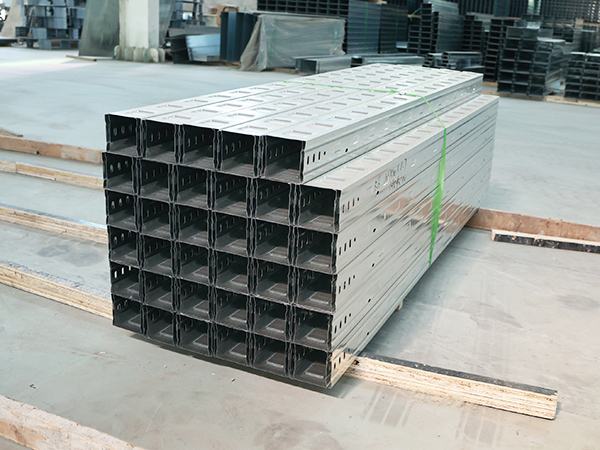
Confirm main keel completion
All main runners must be fully suspended, leveled and locked with double lock nuts on threaded suspension rods. Check no tilting, height deviation or loose U-hangers before installing cross keels.
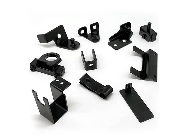
Sort matching keel clips
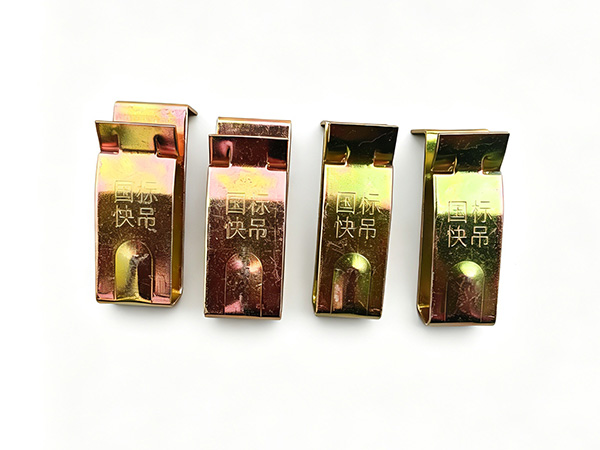
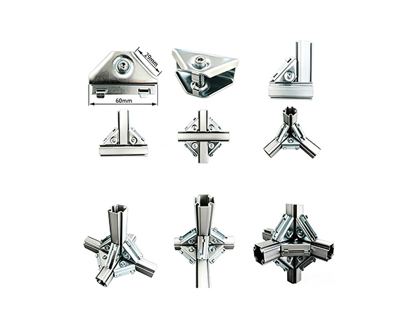
Concealed gypsum ceiling: Furring channel clips corresponding to D38/D50/D60 main runner width and 22/35/68mm cross furring channels; prepare single-lock standard clips and double-lock reinforced clips for heavy-load zones.
Exposed T-grid ceiling: Cross tee hook clips matching 15mm/24mm wide-face main tees.
Mark fixed spacing positions
Draw uniform tick marks along each main runner:
Gypsum board ceiling: Cross keel spacing 400mm center-to-center
600×600 mineral tile T-grid ceiling: Cross tee spacing 600mm
Prepare auxiliary tools: Needle-nose pliers, rubber mallet, laser level for flatness recheck.
Part 1: Connection Steps for Concealed Light Steel Main & Cross Keel (Gypsum Ceiling)
Step 1: Mount furring channel clips onto main runners
Hold one keel clip, slightly open the upper clamping bayonet by hand or needle-nose pliers.
Hook the upper notch firmly onto the bottom flange of the main runner, slide the clip to the pre-marked position.
Press the spring buckle until the clip fully wraps the main keel flange and clicks into locked position; shake lightly to confirm no horizontal sliding.
Repeat installation of all clips along every main runner at standard intervals. Add extra clips around embedded lamps and air outlets to narrow spacing to 300mm for reinforcement.
Step 2: Insert cross furring channel into clip lower slot
Lift a whole cross keel section and align both ends with the lower opening of paired clips on two parallel main runners.
Push the cross furring upward fully into the clip’s bottom clamping groove until the top surface of the cross keel fits flush against the inner support of the clip.
Tap the cross keel gently with a rubber mallet if jamming occurs; never use hard metal hammers to avoid bending clips or scratching the galvanized anti-rust layer. Ensure no gaps or partial disengagement between cross keel and clip.
Step 3: Lock spring tabs for secondary anti-drop safety
Use needle-nose pliers to squeeze the outer elastic spring tab of each clip inward to form a double-lock structure. This step prevents cross keels from slipping down under temperature expansion, long-term vibration or minor seismic shaking, which is mandatory for public offices, high-rise and seismic zone buildings. Visually inspect all joints; replace deformed clips with failed spring elasticity.
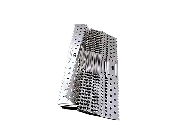
Step 4: Splice extended cross keels with splice connectors
When a single cross keel length cannot cover the full ceiling width:
Align two cross keel ends and insert both sides into a dedicated cross channel splice joint, with overlapping length over 30mm.
Fasten the splice accessory and keel with galvanized self-tapping screws to avoid separation under load.
Stagger all cross keel splice joints and avoid arranging multiple joints on one straight line to prevent concentrated stress and grid deformation.
Step 5: Reinforcement for special ceiling conditions
Double-layer fireproof gypsum ceilings: Replace standard single clips with thickened double-lock reinforced keel clips to improve bearing capacity.
Multi-layer curved modeling ceilings: Adopt customized widened bent clips to fix arc-shaped cross keels and maintain smooth radian.
Large-span ceilings over 4m: Install auxiliary wall angle brackets at cross keel ends for lateral support.
Part 2: Connection Steps for Exposed T-Grid Main Tee & Cross Tee (Mineral Tile Ceiling)
Step 1: Hook cross tee clips onto main tees
Hang special cross tee hook clips onto the bottom flange of main tees at every 600mm marked interval. The hook structure locks automatically after hanging without extra spring squeezing.
Step 2: Buckle cross tees into hook clips
Insert both ends of cross tees into the lower bayonet of paired hook clips, push downward until fully engaged. The interlocking structure forms a standard 600×600 or 600×1200mm square grid for ceiling tiles.
Step 3: Connect short cross tees with cross tee splices
Use dedicated cross tee joint connectors to splice short cross tees on long wall sides, ensure tight joint fit without gaps.
Step 6: Post-Connection Flatness Inspection
Turn on the laser level to scan the entire cross keel grid and check uniform horizontal height.
Push each cross keel lightly by hand; qualified connection shows no shaking, bouncing or vertical displacement.
Readjust loose clips and re-lock spring tabs before installing gypsum boards or mineral tiles.
Common Connection Mistakes to Avoid
Skip spring locking tabs: Cross keels risk falling after years of temperature change and vibration.
Uneven clip spacing: Uneven force distribution causes gypsum board cracks and local sagging.
Incomplete insertion of cross keels into clip slots: Creates weak supporting points under panel weight.
Mix mismatched size clips and keels: Poor clamping force leads to keel dislocation.
Thin low-cost electroplated clips with softened springs: Loosen quickly in humid environments.
Conclusion
The standard connection logic for ceiling main and cross keel is uniform for all ceiling types: install matched keel clips on main runners at standard intervals → embed cross keels into clip lower slots → lock elastic spring tabs for anti-drop safety → splice short cross keels via joint connectors and reinforce heavy-load areas. Fully locked size-matched keel clips guarantee a rigid, flat and safe ceiling grid that meets commercial building load, fire and seismic specifications.
APA 7th
Salkhordeha, M., & Soroushian, S. (2025). Seismic performance of suspended ceiling systems; A literature review. Structural Survey, 43(4), 412–435.
MLA 9th
Salkhordeha, Mojtaba, and Siavash Soroushian. "Seismic Performance of Suspended Ceiling Systems; A Literature Review." Structural Survey, vol. 43, no. 4, 2025, pp. 412–435,
GB/T 7714-2015
[1] SALKHORDEHA M, SOROUSHIAN S. Seismic performance of suspended ceiling systems; A literature review[J]. Structural Survey, 2025, 43(4): 412-435.

- Bazhou Yishun Machinery Parts Co., Ltd
- Contact:Mr Zhao
- Email: 11111111111
- Add: Zhaojiazhuang Village, Bazhou Town, Bazhou City, Langfang City, Hebei Province, China

Copyright © 2025-2026 Bazhou Yishun Machinery Parts Co., Ltd All Rights Reserved