
How to hang main keel with ceiling suspension accessories?
Author:Yishun Time:2026-06-21 14:23:46 Number of views:84Second-rate
Hanging main runners with standard ceiling suspension accessories is the core load-bearing procedure of a suspended ceiling system. Improper assembly of suspension rods, U-hangers and locking fasteners will lead to uneven ceiling elevation, keel sliding, sagging and even structural safety hazards in long-term use. This detailed operation guide covers preparation, step-by-step hanging process, height adjustment and reinforcement standards, complying with international metal ceiling construction specifications (Salkhordeha & Soroushian, 2025).
1. Pre-construction Preparation & Component Inspection
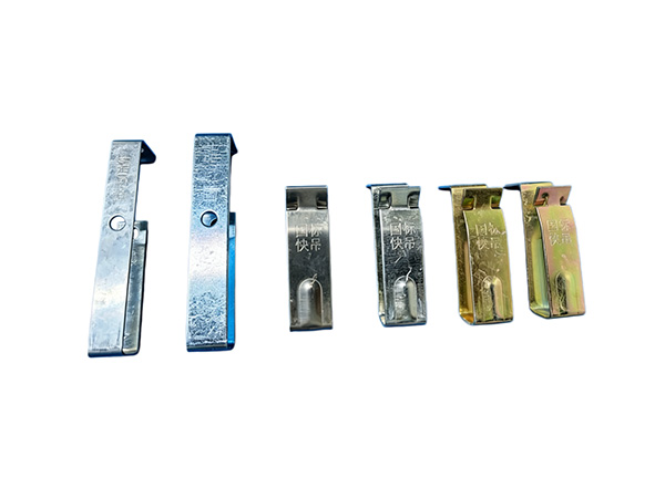
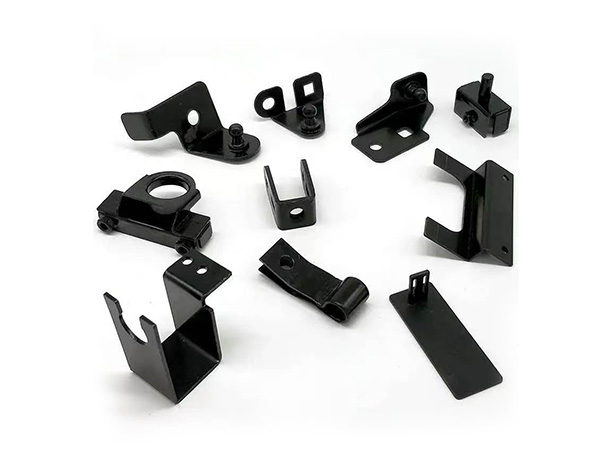
Standard suspension accessory set for main keel includes full-thread suspension rod, expansion anchor bolt, flat washer, lock nut, U-shaped main runner hanger and anti-drop spring clip.
Clean the concrete ceiling and mark suspension point positions according to design spacing (1200mm standard for regular offices; 900mm for fire-rated, seismic or heavy-load ceilings).
Check all suspension accessories: No bending, rust or cracked zinc coating on hangers and threaded rods; threads must be complete for smooth height adjustment.
Prepare tools: Laser level, impact drill, adjustable wrench, measuring tape, marker, wire cutter.
Confirm ceiling design height to pre-cut suspension rods to matched length, reserve 100–150mm extra thread for fine-tuning.
2. Step 1: Fix suspension rod assembly to concrete slab
Drill vertical holes at marked suspension points, hole depth matches expansion bolt size. Hammer expansion anchors firmly into holes until fully embedded.
Thread one lock nut + one flat washer onto the top end of suspension rod, screw the rod into the expansion anchor and tighten the top nut to lock the rod vertically without swaying.
Slide two lock nuts and one flat washer down along the suspension rod; these three parts will clamp the U-hanger to fix main keel later.
Repeat the above operation for all suspension points, ensure all suspension rods keep vertical, no inclined deflection.
3. Step 2: Mount U-type suspension hanger on threaded rod
Lift the U-shaped main keel hanger and pass the suspension rod through the central hole of the hanger. Place the hanger between the upper and lower pre-assembled lock nuts.
Temporarily twist the upper lock nut down to hold the hanger in place; do not fully tighten for the moment to reserve space for horizontal leveling.
Insert anti-drop spring clip into the side notch of the U-hanger. This clip acts as secondary safety protection to prevent the main runner from slipping out of the bracket under vibration or thermal deformation.
4. Step 3: Place main keel into U-hanger and preliminary fixation
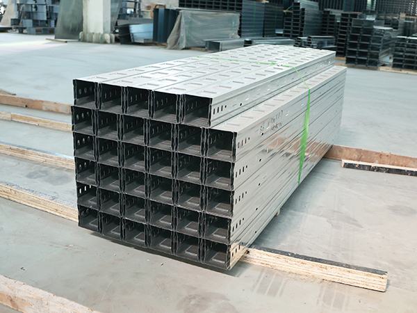
Lift the whole main runner channel and embed its top flange into the U-shaped slot of the suspension hanger. Make sure the keel fits tightly inside the bracket without left-right gap.
Adjust the lower lock nut up to lightly support the hanger bottom, so the main runner can stay stable temporarily.
Align the whole main keel along the pre-marked horizontal layout line; connect multiple main channel sections with splice connectors if length is insufficient, stagger all splice joints to avoid concentrated stress.
5. Step 4: Unified horizontal height adjustment
Turn on the laser level and project a uniform horizontal reference line for the whole ceiling.
Adjust the upper and lower lock nuts of each suspension rod synchronously: Raise or lower the U-hanger to make the bottom surface of all main keels coincide with the laser reference height.
After leveling one suspension point, fully tighten both upper and lower lock nuts to clamp the hanger rigidly; eliminate vertical clearance between nuts and hanger to stop vertical displacement.
Walk along the full length of the main runner and recheck flatness with a straight ruler; adjust any over-high or low suspension points again.
6. Step 6: Reinforcement for special working conditions
Heavy load areas (large LED panels, air duct diffusers, suspended equipment): Add one extra suspension set between two standard suspension points, shorten spacing to 600–900mm, adopt thickened reinforced U-hangers.
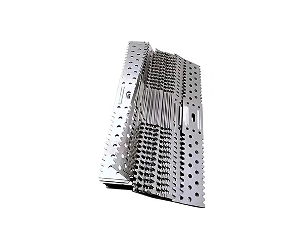
Fire-resistant & seismic public buildings: Install extra seismic lateral support brackets for long-span main keels over 3 meters, lock all suspension joints with anti-sway limit clips.
Multi-level stepped ceilings: Use lengthened customized suspension rods, separately level each layer’s main keel suspension system.
7. Post-hanging Inspection Standards
All U-hangers fully wrap the main keel flange, anti-drop spring clips installed on every hanger without omission.
Double lock nuts tightened on each suspension rod, no loose threads or sliding hangers.
All main keels keep straight and horizontal, height error controlled within ±2mm per 2 meters.
Suspension spacing strictly follows design drawing, extra reinforcement added for heavy-load positions.
Common Mistakes to Avoid
Omit anti-drop spring clips: Risk of main keel falling under long-term vibration.
Only tighten one single lock nut: Hanger will shift vertically after load bearing, causing ceiling unevenness.
Inclined suspension rods: Generate lateral pulling force and deform the whole keel grid.
Mix thin electroplated low-grade hangers: Easy rust and insufficient clamping force for long-term commercial use.
Conclusion
The standard workflow for hanging main keel with suspension accessories follows a fixed logic: Fix vertical suspension rods on ceiling slab → assemble U-hanger and safety clip on rod → embed main runner into hanger → adjust uniform horizontal height via double lock nuts → tighten nuts for permanent fixation plus special reinforcement. Standardized hanging operation guarantees stable load bearing, flat ceiling surface and long-term safe service of the entire suspended ceiling framework.
APA 7th
Salkhordeha, M., & Soroushian, S. (2025). Seismic performance of suspended ceiling systems; A literature review. Structural Survey, 43(4), 412–435. MLA 9th
Salkhordeha, Mojtaba, and Siavash Soroushian. "Seismic Performance of Suspended Ceiling Systems; A Literature Review." Structural Survey, vol. 43, no. 4, 2025, pp. 412–435, GB/T 7714-2015
[1] SALKHORDEHA M, SOROUSHIAN S. Seismic performance of suspended ceiling systems; A literature review[J]. Structural Survey, 2025, 43(4): 412-435.

- Bazhou Yishun Machinery Parts Co., Ltd
- Contact:Mr Zhao
- Email: 11111111111
- Add: Zhaojiazhuang Village, Bazhou Town, Bazhou City, Langfang City, Hebei Province, China

Copyright © 2025-2026 Bazhou Yishun Machinery Parts Co., Ltd All Rights Reserved