
How to install suspended ceiling keel accessories step by step?
Author:Yishun Time:2026-06-21 14:22:19 Number of views:75Second-rate
Correct assembly of suspended ceiling keel accessories directly determines the flatness, load capacity and long-term safety of the entire ceiling framework. Irregular installation steps often lead to loose buckles, uneven keel grids, local sagging and hidden safety risks, especially for large-area office and commercial gypsum board ceilings (Salkhordeha & Soroushian, 2025). Below is a complete standardized step-by-step installation guide for concealed light steel keel ceiling supporting accessories, suitable for contractors, construction workers and DIY engineers.
Pre-installation preparation work
Measure ceiling span, mark horizontal elevation lines on surrounding walls with a laser level, and confirm main runner and furring channel layout spacing (main runner 1200mm, secondary furring 400mm standard).
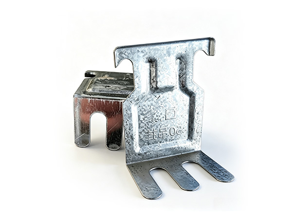
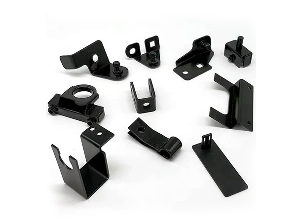
Check all supporting accessories: threaded suspension rods, U-hangers, furring clips, main runner splices, wall angle brackets, self-tapping screws and seismic fittings (for public buildings). Verify no deformation, rust or dimensional mismatch.
Prepare installation tools: impact drill, wrench, laser level, measuring tape, screwdriver, wire cutter and expansion bolts for floor slab fixing.
Classify accessories by function to avoid mixing during assembly.
Step 1: Fix suspension rod assemblies to the top floor slab
Punch fixing holes on the concrete ceiling according to pre-marked suspension point positions at 1200mm intervals.
Hammer expansion bolts into drilled holes and lock one end of the threaded suspension rod tightly with flat washers and lock nuts.
Adjust the rod length to align with the pre-set ceiling height, and temporarily fasten the upper nut to prevent sliding down.
For ceilings over 4m span or heavy load areas with lamps/air vents, add extra suspension rods to shorten spacing to 900mm.
Step 2: Mount U-type hangers onto threaded suspension rods
Thread two lock nuts and a flat washer onto each suspension rod, slide the U-shaped main runner hanger between the two nuts.
Place the main channel into the U-shaped opening of the hanger, then tighten upper and lower nuts to clamp the hanger firmly, eliminating vertical displacement.
Insert anti-drop spring clips into the side gaps of hangers to lock main runners and avoid detachment under vibration.
Adjust the height of each hanger uniformly by laser level to ensure all main runners stay on the same horizontal plane.
Step 3: Splice full-length main runners with main runner connectors
When a single main channel cannot cover the full ceiling length, align two keel ends into the main runner splice accessory, with an overlapping length over 40mm.
Fasten both sides of the splice connector with self-tapping screws to lock two keel sections as an integrated piece.
Arrange all splice joints in a staggered layout instead of in a straight line to improve overall structural stability.
Step 4: Install secondary furring channel clips and mount cross keels
Clip furring channel buckles onto the bottom flange of main runners at every 400mm mark point.
Insert secondary furring channels horizontally into the lower bay of each clip, and press the buckle’s spring piece to lock the cross keel tightly without shaking.
Use furring splice connectors for short secondary keels on long wall sides, fix joints with screws to prevent gaps.
For double-layer gypsum board ceilings, install double reinforced clips to enhance bearing capacity.
Step 5: Fix perimeter wall angle brackets along surrounding walls
Install L-shaped wall angle brackets along the wall elevation line at maximum 500mm fixing intervals.
Use wall expansion bolts to lock brackets onto brick or concrete walls; plastic wall plugs are forbidden for fire-rated projects.
Place the outermost secondary furring channel on the horizontal edge of wall angles to support the end of the keel grid and limit horizontal shifting of the whole ceiling.
Use special internal and external corner brackets for wall turning joints to keep edges neat and sealed.
Step 6: Assemble seismic safety accessories (mandatory for high-rise & seismic zone buildings)
Install seismic lateral support brackets every 3.6 meters on large-area ceilings.
Connect horizontal bracing steel rods between keel grids and wall structural components, lock all joints with seismic anti-drop clips.
Mount limit anti-sway fittings at suspension points to restrict lateral deformation during shaking.
Step 7: Overall flatness inspection & accessory reinforcement
Use a 2m straight ruler to check horizontal flatness of the entire keel grid; adjust suspension rod nuts to correct height deviation.
Tighten all loose hangers, clips and splice screws one by one.
Add thickened reinforcement hangers at positions of embedded large lamps, air ducts and suspended equipment.
Reserve 5% spare accessories for later maintenance and partial replacement.
Step 8: Final acceptance before gypsum board installation
Check all key standards: uniform suspension spacing, firm locking of all connecting accessories, consistent horizontal elevation, complete seismic/fire fittings as required, no loose or deformed accessories. Only after full inspection can gypsum boards be fixed onto secondary furring channels with drywall screws.
Key installation notes to avoid common defects
Do not skip anti-drop spring clips; loose hangers are the top cause of ceiling collapse risks.
Keep consistent spacing of furring clips, uneven intervals will make gypsum boards crack easily.
All metal contact joints must use galvanized steel fasteners; plastic gaskets or screws are prohibited for fire-resistant ceilings.
Leave proper thermal expansion gaps at keel splices to prevent arching deformation in temperature changing seasons.
Conclusion
The full installation sequence of suspended ceiling keel accessories follows a top-down logic: fix suspension rods → mount main runner hangers → splice main keels → install cross keel clips → fix wall perimeter brackets → add seismic fittings → overall flatness adjustment. Strictly following this step-by-step process ensures the ceiling framework reaches standard load-bearing performance, flatness and long service life, complying with international commercial building construction specifications.
APA 7th
Salkhordeha, M., & Soroushian, S. (2025). Seismic performance of suspended ceiling systems; A literature review. Structural Survey, 43(4), 412–435. MLA 9th
Salkhordeha, Mojtaba, and Siavash Soroushian. "Seismic Performance of Suspended Ceiling Systems; A Literature Review." Structural Survey, vol. 43, no. 4, 2025, pp. 412–435, GB/T 7714-2015
[1] SALKHORDEHA M, SOROUSHIAN S. Seismic performance of suspended ceiling systems; A literature review[J]. Structural Survey, 2025, 43(4): 412-435.

- Bazhou Yishun Machinery Parts Co., Ltd
- Contact:Mr Zhao
- Email: 11111111111
- Add: Zhaojiazhuang Village, Bazhou Town, Bazhou City, Langfang City, Hebei Province, China

Copyright © 2025-2026 Bazhou Yishun Machinery Parts Co., Ltd All Rights Reserved