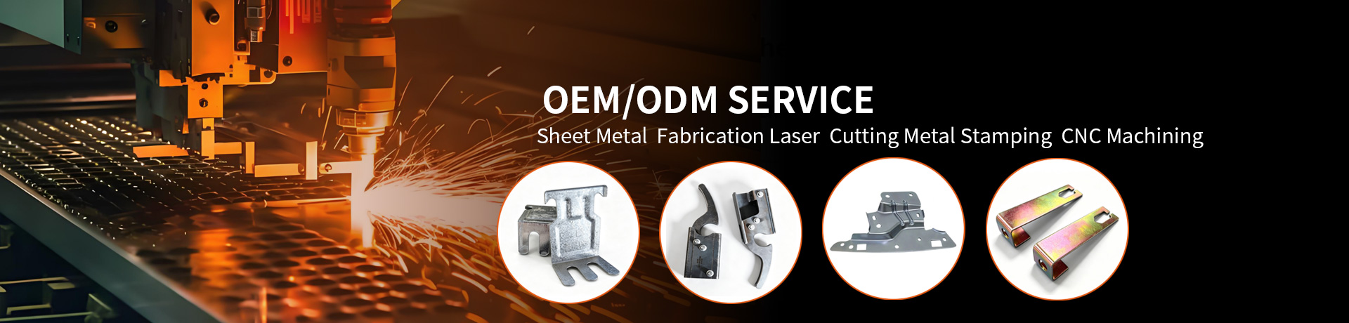
Metal Stamping Parts in Electrical Equipment Manufacturing
Author:yishun Time:2026-10-30 16:41:43 Number of views:142Second-rate

Almost every piece of electrical equipment contains stamped metal. The terminal that a wire crimps into, the busbar that carries current, the shield that suppresses interference, and the enclosure that houses it all began as flat strip fed through a press. Stamping is the dominant way industry turns sheet and strip metal into the small, precise, high-volume conductive and structural parts that electrical products depend on.
This article is for electrical design engineers, OEM sourcing teams, and procurement specialists evaluating custom metal stamping parts. It covers how stamping works, where stamped parts sit inside electrical equipment, the technical trade-offs that decide performance, and what to put on a request for quotation.
Why Stamping Fits Electrical Manufacturing
Electrical equipment needs parts that are conductive, dimensionally consistent, and cheap enough to use by the million. Stamping delivers all three:
High volume at low unit cost. Once the tool is made, each stroke of the press yields a part, so per-piece cost falls sharply at volume.
Tight, repeatable tolerance. A hardened die holds geometry part after part, which matters for mating connectors and contact springs.
Material efficiency. Blanking and progressive layouts nest parts to minimize scrap from expensive copper and plated strip.
Formability. The same process can cut, bend, and form in one sequence, producing springs, tabs, and clips without assembly.
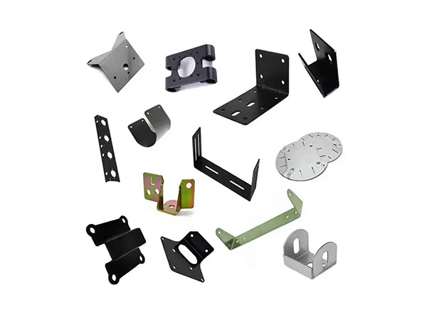
How the Stamping Process Works
Stamping converts coil or strip stock into shaped parts using a press and die. The operations most relevant to electrical parts are:
Blanking — cuts the part (or a blank) out of the strip. The cut edge is the part's outer profile.
Piercing — punches holes, slots, or windows (for terminals, mounting, or wire entry).
Bending / forming — creates angles, tabs, springs, and clips. Springback (the metal's tendency to relax after bending) must be designed out.
Drawing — pulls flat stock into a cup or shell, used for some enclosures and sensor cans.
Progressive die stamping — performs several operations at successive stations in one pass, ideal for high-volume terminals and connectors.
In a progressive die, the strip advances station by station; by the final station a finished part is ejected and the web continues. This is the workhorse for connector and terminal production.
Where Stamped Parts Appear in Electrical Equipment
Terminals and lugs
Crimp terminals, blade terminals, and lugs are stamped from copper or brass strip, then often plated. The stamped geometry defines the crimp barrel, the insulation support, and the mating tongue. Dimensional control here decides connection reliability.
Connectors and contact springs
Pin and socket connectors, contact beams, and spring fingers are stamped to hold precise contact force. A fraction of a millimeter in beam position changes insertion force and long-term contact resistance.
Busbars and current carriers
Flat or formed busbars are stamped (or stamped and bent) from copper or aluminum to route current with low resistance. Holes, bends, and mounting features are produced in one sequence.
EMI / RFI shields
Shield cans and finger-stock are stamped from conductive, sometimes beryllium-copper or spring steel, then formed to enclose sensitive circuits. The shield's seam and contact points are stamping-critical.
Enclosures and brackets
Panel enclosures, DIN-rail clips, and mounting brackets are stamped and bent from steel or aluminum, frequently with a protective finish. These carry both structure and grounding.
Heat sinks and contact components
Some heat-sink features and thermal contacts are stamped or stamped-and-formed, trading the cost of extrusion for high-volume simplicity where performance allows.
The design choices behind these parts — geometry, material, and tolerance — are explored further in how design impacts metal stamping part performance, and surface treatment options are covered in surface finishing options for metal stamping parts.
Material Selection — Conductivity vs. Strength vs. Cost
Electrical stamping lives at the intersection of three properties:
Conductivity. Copper (e.g., tough-pitch C11000) and its alloys carry current efficiently; brass and bronze trade some conductivity for strength and spring.
Spring properties. Contact beams need a material that resists permanent set — copper alloys such as C194 or beryllium-copper families are common where a spring function is required.
Formability and cost. Steel and aluminum stamp cleanly and cheaply for structural and enclosures parts where conductivity is not the priority.
Plating (tin, silver, nickel, or gold flash) is then added for solderability, corrosion resistance, or low contact resistance. The base metal and the plating are separate decisions and should be specified separately.
Technical Points That Decide Performance
Tolerance and flatness
Mating features need tight positional tolerance; formed springs need controlled bend angles. State tolerances per feature, not one blanket number, and align them with what the die can hold economically.
Burr and edge quality
The blanking direction leaves a burr on one edge. For terminals and contacts, burr height and direction affect crimp quality and safety. Specify maximum burr and which edge faces the mating part.
Springback control
Bent features relax after the punch retracts. The die is usually pre-compensated, but material temper and thickness variation shift the result. Confirm with a first-article check against a formed-sample.
Plating adhesion and thickness
For conductive parts, plating thickness drives contact resistance and solderability; adhesion drives field reliability. Reference a recognized plating specification rather than describing it loosely.
Residual stress and cracking
Aggressive bends on hard tempers can crack at the grain boundary. Specify bend radius relative to thickness and the material temper to avoid it.
Compliance and Documentation
Electrical parts often ship into regulated markets. Two substance-restriction regimes appear frequently:
RoHS (Restriction of Hazardous Substances) — limits substances such as lead, cadmium, and certain flame retardants in electronics placed on many markets.
REACH — the EU chemicals regulation covering registration and restriction of substances; relevant to plating and coating chemistry.
Confirm the applicable regime with your compliance team and request material declarations from the supplier. These are documentation items, not performance items, but they gate market access.
How to Specify and Procure Stamped Electrical Parts
A good RFQ lets the supplier quote a part that will actually perform. Include:
A dimensioned drawing with critical-to-function tolerances called out separately.
Material specification — base alloy and temper, plus plating type and thickness.
Volume and forecast — this decides whether a progressive die (high tooling cost, low unit cost) or a simpler setup is right.
Critical features — contact surfaces, crimp barrels, spring beams — with the test or gauge that proves them.
Compliance requirements — RoHS/REACH declarations, conflict-minerals, or other market mandates.
Packaging and traceability — reel vs. bulk, barcode, lot traceability for field failures.
For prototypes, expect a soft-tool or laser-cut sample before committing to hard tooling; for production, expect a first-article inspection (FAI) report and periodic capability data.
Common Pitfalls
Designing for machining, not stamping. Sharp internal corners and impossible tolerances raise cost; radii and strip-friendly geometry cut it.
Under-specifying plating. "Plate it" is not a spec; state alloy, thickness, and where.
Ignoring springback. Assuming the bent angle equals the drawing angle causes field fit problems.
Volume mismatch. Ordering a progressive die for a low-volume part wastes tooling budget; ordering soft tooling for a high-volume part inflates unit cost.
Note on alloys and standards: Specific alloy designations (such as C11000, C194) and temper call-outs should follow the recognized standard applicable to your market (for example ASTM or equivalent national standards). Confirm the exact grade with your supplier's material certificate rather than relying on a generic name.
FAQ
Why are most electrical terminals stamped rather than machined?
Stamping produces millions of identical parts at low unit cost with repeatable tolerances, which machining cannot match economically at volume. The trade-off is higher upfront tooling cost.
What material is best for a spring contact?
A copper alloy with good spring properties (for example C194 or a beryllium-copper family) is typical where the part must hold contact force without taking a permanent set. The final choice balances conductivity, spring, and cost.
Does burr direction matter on a terminal?
Yes. The burr from blanking sits on one edge; if it faces the crimp or mating surface it can raise resistance or cut the wire strand. Specify maximum burr height and orientation.
When should I use a progressive die?
When volume is high enough to amortize tooling — progressive dies excel at millions of terminals and connectors. For prototypes or low volume, soft tooling or laser cutting is usually cheaper overall.
Do stamped electrical parts need RoHS compliance?
If they ship into markets that enforce RoHS (and similar regimes such as REACH for chemicals), then yes — compliance and a material declaration are typically required. Confirm the applicable market with your team.
Conclusion
Metal stamping is the quiet enabler of electrical equipment: it turns conductive strip into the terminals, connectors, busbars, shields, and enclosures that products are built from, at the tolerance and cost volume demands. Performance is set early — by material choice, by tolerance and burr control, by springback compensation, and by plating specification — and locked in by the die. Engineers and buyers get the best result by treating stamped parts as designed components: send a clear drawing, specify base metal and plating separately, match the tooling to the volume, and require the compliance documentation the market expects. Do that, and stamping delivers consistent, reliable, affordable electrical parts.
Technical References
Wikipedia — Stamping (metalworking) (process overview of blanking, piercing, bending, and progressive dies).
ASTM International — astm.org (standards for copper alloys, strip temper, and plating used in electrical stamping).
Wikipedia — Beryllium copper (background on spring-grade copper alloys used in contacts).
European Chemicals Agency (REACH) — echa.europa.eu (substance regulation relevant to plating and coatings).
The Fabricator — thefabricator.com (industry coverage of progressive-die design and tolerance practice).

- Bazhou Yishun Machinery Parts Co., Ltd
- Contact:Mr Zhao
- Email: ziyangzhao96@gmail.com
- Add: Zhaojiazhuang Village, Bazhou Town, Bazhou City, Langfang City, Hebei Province, China

Copyright © 2026-2027 Bazhou Yishun Machinery Parts Co., Ltd All Rights Reserved